An ancient proverb says that power tool failures occur in threes. During the same week that the lathe motor burned out and the compressor wire meltdown has turned it into a scary noise machine, we also had a mysterious malfunction in one of our welders. It didn’t release any smoke, didn’t make weird noises. It just didn’t weld. 0 volts across the output.
This machine, a small 180A TIG/MMA inverter welder, has recently been repaired. It was not used heavily, as TOG has only so much use for welding. In fact, it was only used by a couple members to practise their welding skills.
On one hand, this machine was 5 year old, has been used extensively in the past and could have been written off as death of old age. The cost of a commercial repair would probably exceed the value of the welder. On the other hand – why not try to repair it ourselves before scrapping it?
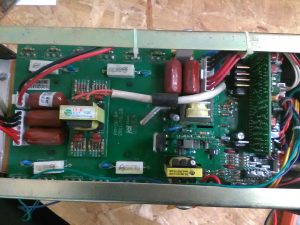
So, first pass – take it apart and look for obvious damage, like blown up MOSFETs or rectifier diodes. Nope, nothing there. All power resistors look intact, too. All cables securely plugged in. No charred FR4. Nothing clearly damaged or even suspiciously-looking.
What next? Seems hopeless. First, we don’t know how an inverter welder works exactly. Second, we don’t want any deaths, either from electrocution or any other reasons.
The safety problem was somewhat addressed by setting up all the probing while device was unpowered – both in terms of mains and its storage capacitors. The device was only powered for a few seconds to read the measurements off the screen, without touching anything. All measurement instruments were battery-operated, to avoid unintended coupling through protective earth in mains-operated instruments. This approach doesn’t really avoid all dangers, but at least addresses the well-known risks.
The lack of knowledge issue is solved by a rabid and desperate search for any possible schematics and repair hints, from Chinese search engines to Polish electronics repair forums and, of course, various chip manufacturer datasheets. Turns out that many of the MMA and TIG machines from the last decade are variants of the same 3-board design (+daughterboards). We haven’t found the schematic for the machine in question but we didn’t really need it – a PDF schematic of a 160A MMA welder found using Chinese image search was very helpful in identifying major blocks and their connections. A TIG machine obviously contains more logic to handle the TIG functionality (gas valve, pulsing, HF/HV arc start etc.) but those were ruled out as a likely root cause.
All of those welders have a common set of functional units. A primary-side rectifier on a lower board rectifies the 230V mains voltage and provides slow-start functionality to prevent power surges. A power MOSFET module on the top board does all the switching work. Then there’s a set of transformers and secondary rectifier diodes on the middle board that provides output DC voltage for welding, with help of some power chokes to filter out the switching AC component. The whole switching process is controlled by a drive module on a vertical daughterboard, which in turn feeds a H-bridge of small MOSFETs that feeds a transformer that provides gate voltages with correct polarity for all the power transistors. Sounds complicated, but at least everything is nicely divided into modules with a well-defined purpose each. The drive circuit is powered by an auxiliary 24V power supply that turned out to be one of the known weak spot in these units, according to some forum posts.
So, the investigation first looked at the output voltage from the power MOSFETs. There was none. Input voltage for that block – present. So, it will likely be something between the primary rectifier and the output from the MOSFET module. Broken MOSFETs? Nope, they measure fine. Is there a gate signal? Nope. Not on the power MOSFETs themselves, and not even in the H-bridge that is driving the gate-drive transformer. So, perhaps it’s the drive module. After a few hours of connecting alligator clips to various points (heavily coated in non-conducting lacquer, by the way) it was apparent that the SG3525A that was supposed to generate signal that (eventually) drives the power MOSFETs was shut down by one of three protection circuits. There are several: overheating protection (based on temperature switch) – certainly not an issue here. Overcurrent protection – also not to blame here. The one that turned out to be responsible was the undervoltage protection for the 24V supply. Why is too low a voltage a problem? because keeping switching MOSFETs in active region instead of saturation makes them overheat and fail very quickly – and insufficient gate drive prevents saturation. And, bingo – the aux supply voltage was definitely below the usual 24V. The actual value depended on which modules have been left connected – with TIG timing board connected it dropped to almost 12V! Without it was still 19V or so – so, it was definitely a wimpy power supply issue, not, say, a short on the TIG timing board. Trying the welder with 24V supplied from outside (via isolated lab supply) confirmed no other faults – the machine seemed fully working with that setup.
The 24V supply is a flyback converter, based – in this case on a UC3843 PWM chip. In other welders, it may be a bunch of discrete components instead. The converter is using a 200:33:33:16 transformer. One secondary winding used to provide the output voltage, which is then rectified and compared to 24V threshold, with feedback given via an optoisolator. Another, smaller secondary is used to power the PWM chip itself, with help of a standard rectifier diode and a filtering capacitor – although the initial voltage is provided with a high-value high-wattage resistor directly from 310V. There’s also a current sense on the primary that limits the current going through it to 1V/2.2ohm =~ 0.45A. The initial suspicion was that the transformer had burned windings which didn’t provide enough current. However, this turned out to be incorrect. The transformer looked perfectly, and replacing it “just in case” would involve waiting and risking damaging the board, already damaged a bit by a careless replacement of a perfectly well-behaved filtering capacitor.
A careful observation with an oscilloscope revealed that the voltage on the Vcc of the UC3843 was drooping as the chip was outputting PWM pulses, getting below the undervoltage lockout of the UC3843, then recovering slowly after some time. So, that small secondary winding wasn’t providing enough power through the diode. But why? Bad transformer? The diode itself tested perfect.
What ended up being the root cause was a broken track on the PCB, between the diode and the rest of the Vcc-related circuitry. So, the PWM chip was only powered through a high-value resistor and running out of power quickly as it started generating the PWM pulses, without getting any extra power via the aux secondary. This caused a weird “a bunch of pulses, then silence, then the cycle repeats” behaviour seen on the oscilloscope, correlated with variations in chip’s Vcc. A piece of wire to mimic the function of the broken trace fixed the 24V output and allowed the rest of the machine to work correctly.