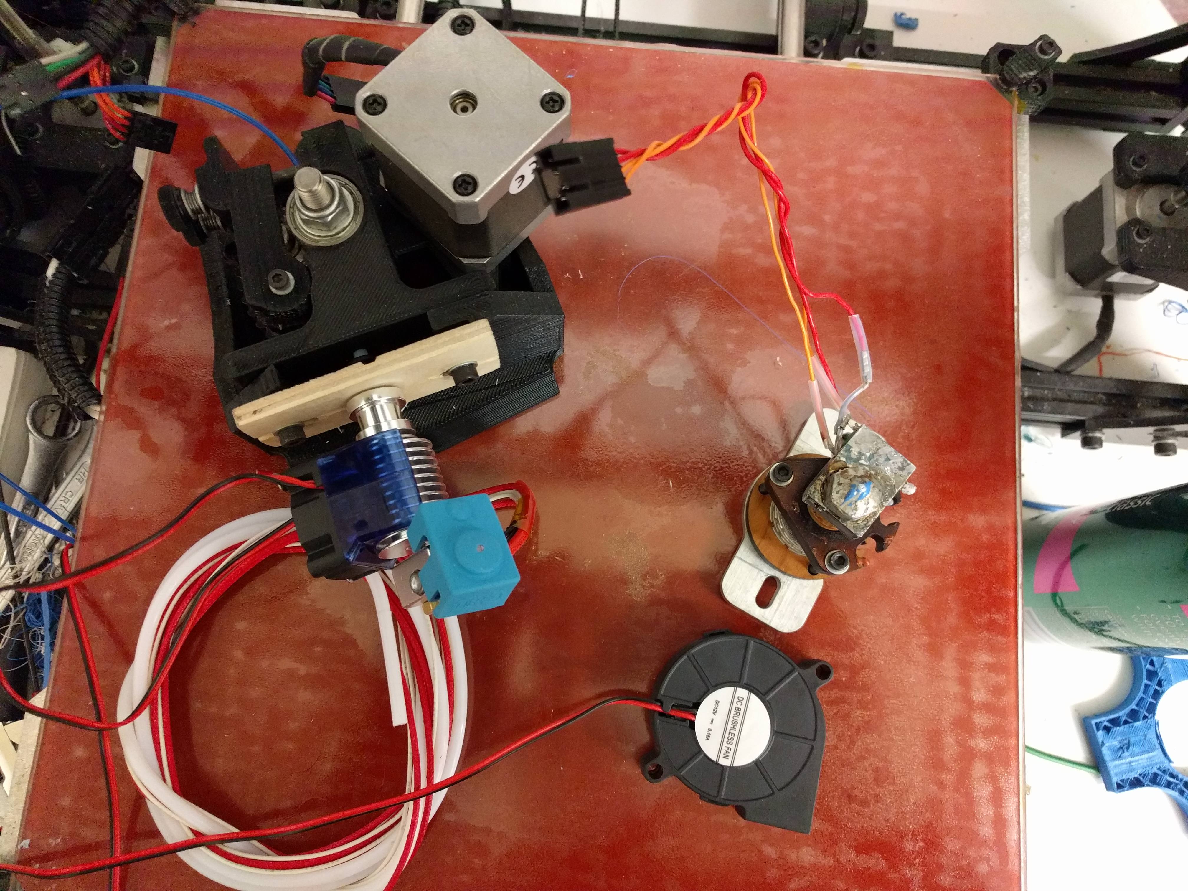
After some TLC was offered up to Tog’s 3D printer, by way of a little restoration and tuning, it became very clear that the current hotend was on its way out.
Tog’s Lulzbot Taz 3.0 FDM 3D Printer has been deprecated and is approximately 3 versions behind the current technology. What’s worse is that the nozzles for the extruder were not standardised, byt comparison the E3D V6 style hotend and nozzles have been almost universally adopted. Even by manufacturers.
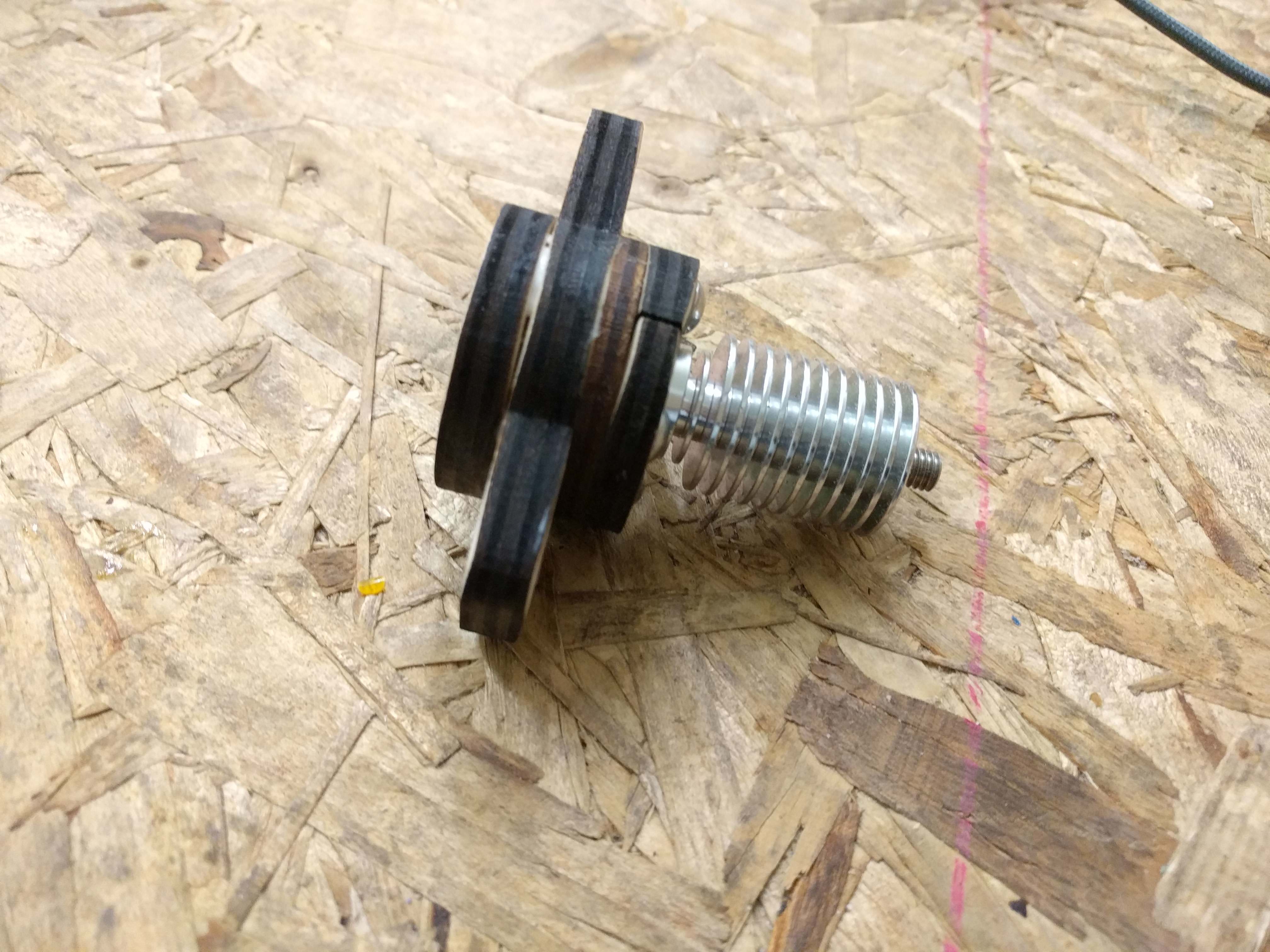
So, in case you’ve been wondering why Tog’s 3D printer has been out of action for approximately the past 2 weeks, thats why. I have started the process of upgrading the extrusion system to use an E3D V6 style hotend. Initally I tried some chinese clones (the designs are GPL’d after all!) but found their quality seriously wanting. I cannot comment on the genuine article as the order appears to have been lost in the UK postal system for the time being.
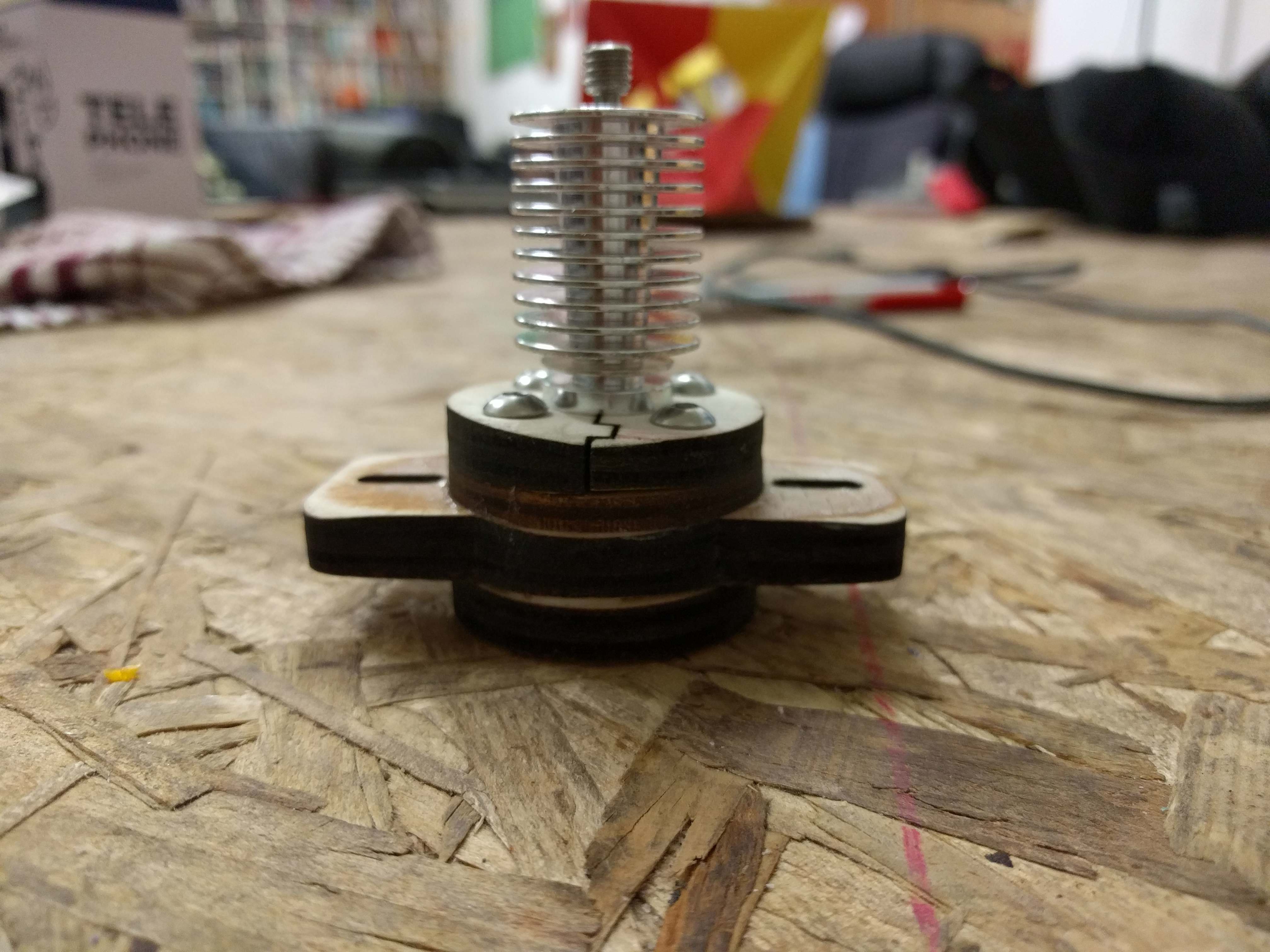
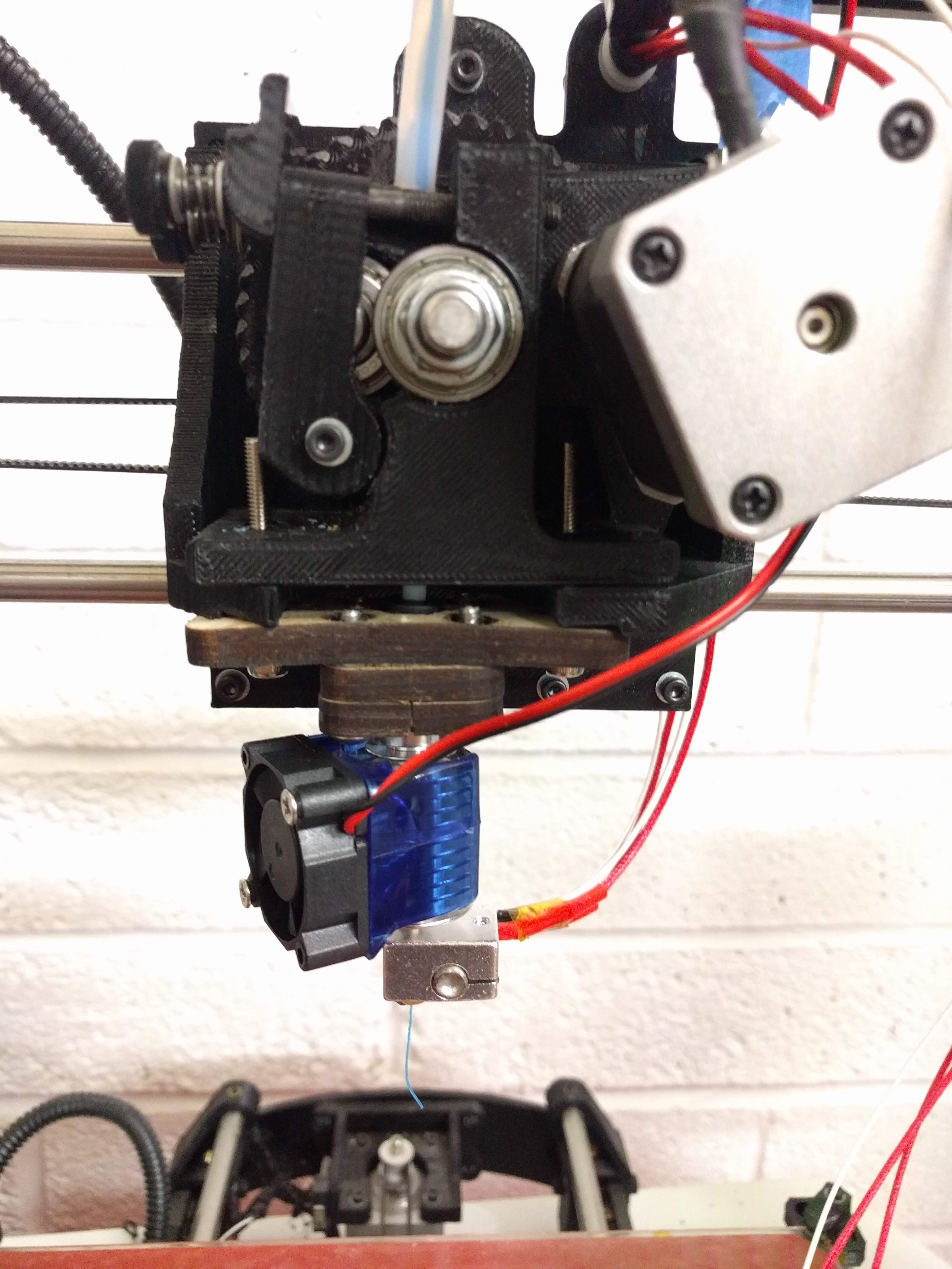
The main issue with changing from the Lulzbot Budaschnozzle v2.0 configuration to an E3D V6 is that there is apparently no models or designs we can draw from to make a mount. So I had to design one from scratch. I say design one, but actually there were many designs. The first was a laser cut wood mount – It worked but it just didnt feel like it what I was experiencing was truely level.
As I am lucky enough to have a Prusa i3 MK3 printer of my own, so I have been iterating over the design and protyping a lot of different variations to see what works. When I say a lot, I do really mean a lot…
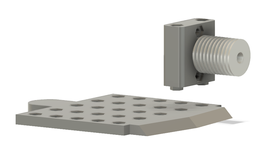
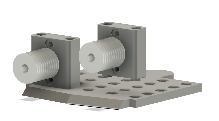
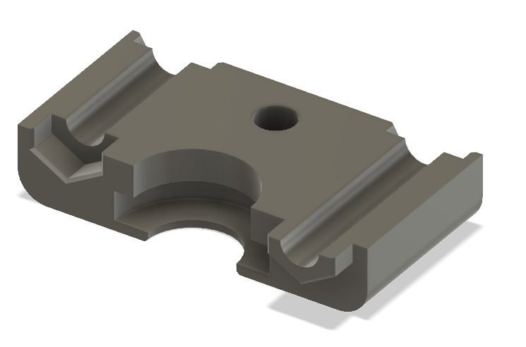
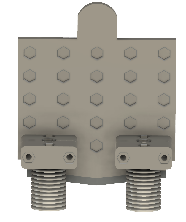
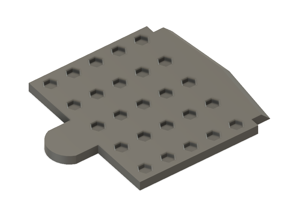
I think now I have finally I settled on this design:
V6_Carriage_2018-Jul-06_04-14-49AM-000_CustomizedView23953781620
The current backplate – which is already a reasonably good hot-plug-able system, is replaced with an altered one. This new one comes with a 5 x 7 grid (14mm spacing) of 4mm hex cavities which will be used as a ‘mechanical key’ to home whatever tool is installed. This way we come a little bit closer to achieving “true level”, mostly. It also has the added feature of supporting many different applications in the one piece – wheras originally it only supported the extruder assembly and the stock nozzle, this new design could even be used for things such as drawing circuits or as a plotter.
As I’ve been using AutoDesk Fusion 360 to design it, you can use this link to see the current model and download it if you so desire. It is still very much a work in progress, however.


 Check out some
 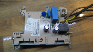 We are no stranger to appliance repairs at TOG. In the past we have taken part in