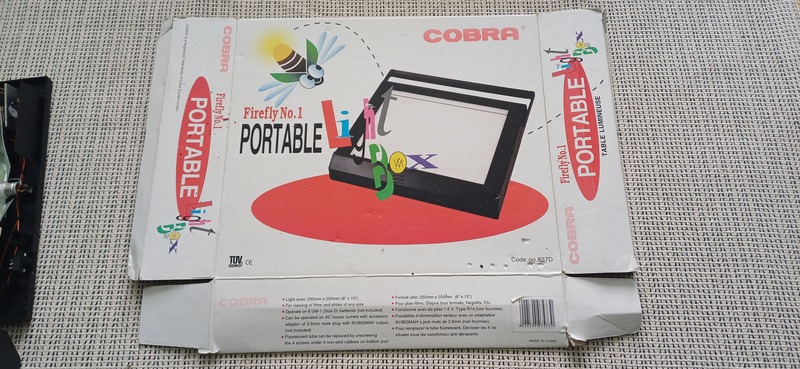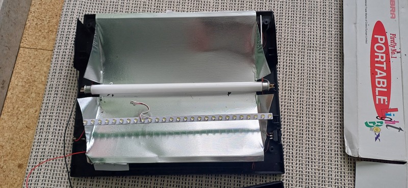
USB-C conversions are becoming a bit of a thing around here. We repaired a faulty work light earlier this year, and we took the opportunity to upgrade the charging socket to USB-C. A few other items have had the same treatment over the last few months. This latest one is an old-school light box for viewing film negatives and slides. We’re still keen on our film photography at TOG, and we still have all of our dark room equipment.
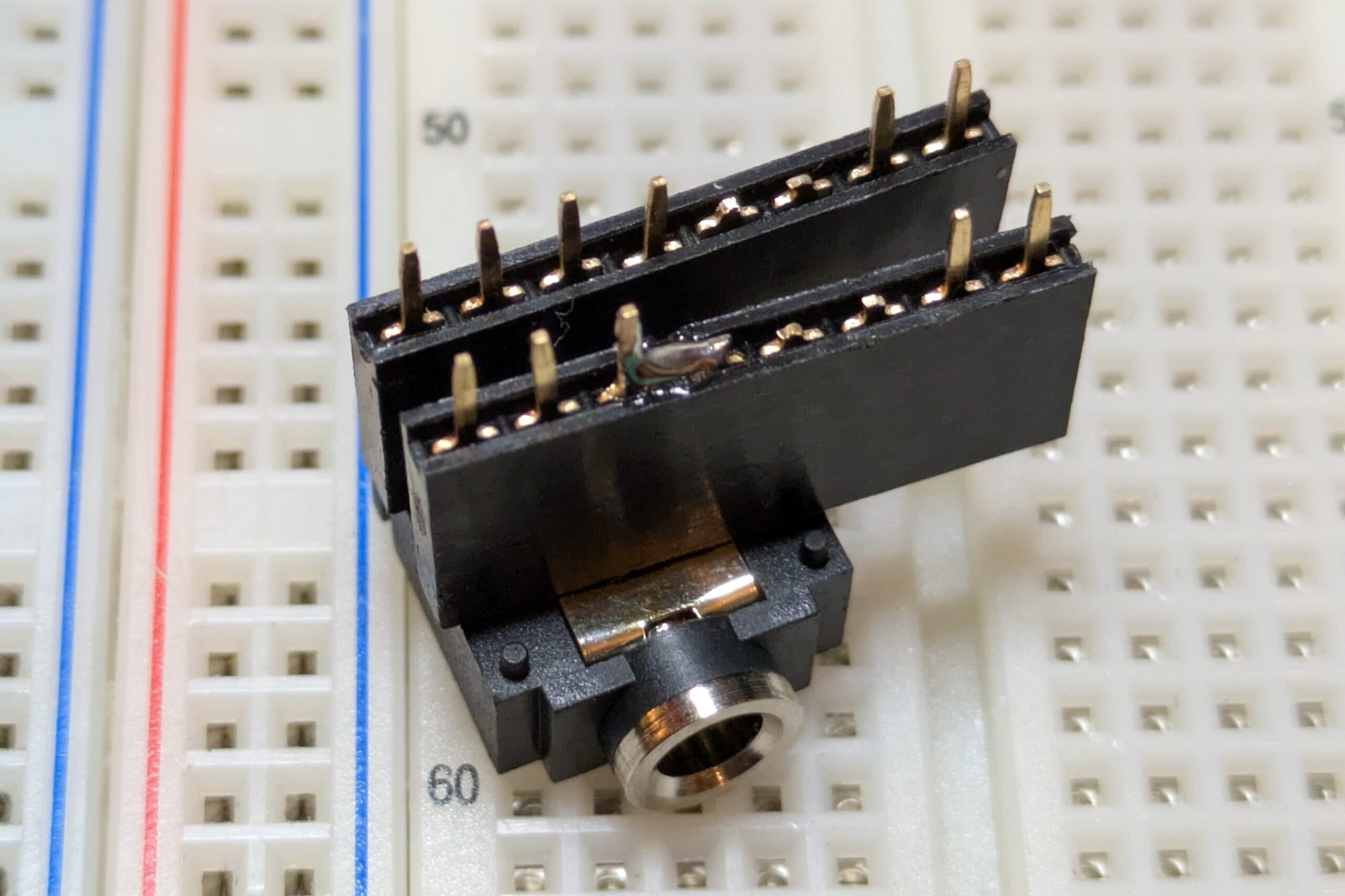
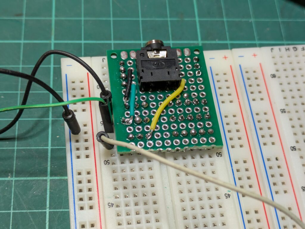
As-built, this particular light box came with with a foot-long fluorescent tube. Inside, there is a driver PCB for the tube, and a 6x D-cell battery compartment. It also has a 3.5mm power input socket if you want to run it from some kind of adapter.
The small driver PCB inside takes the ~9V battery voltage and bumps it up to the high voltage required to to run the fluorescent tube. The switching transistor on the driver has already failed once in the past, and its heat sink gets very hot during operation. Probably not a very optimal design or power efficient.
A bit of work with a Dremel and we have a nice oval hole for the new USB-C socket. A few touches with a soldering iron to melt the plastic, and the socket is now joined firmly to the case. The intention was to feed in 5v, and then bump it up to something closer to 12v to charge the batteries via a current limiting resistor. A cheap voltage converter sourced from the usual websites would look after that.
That was the intended upgrade, but a bit of feature creep came along last night. We thought that it would be nice to replace the fluorescent lamp with a more power efficient LED one. This would also allow us to eliminate that iffy driver PCB. Rummaging around the space, an old emergency light fitting had a nice LED strip ripe for harvesting. Check back in with us over the next while to see the finished article. If you have anything that you think might benefit from a USB-C upgrade, drop in to our regular Monday and Tuesday open nights.