A call went out this festive period on the Irish Makers Unite discord server, looking for interest in participating in a Secret Santa project. Our own Jeffrey Roe decided to take part and this is blog post about his build.
The rules of the project were simple: the gift had to be made by the maker. I received a small blurb about the maker I was creating for. They asked for a desk toy. Due to other commitments, I left myself with only two days for the build, so all the parts would need to be from what I have at home or in the hackerspace.
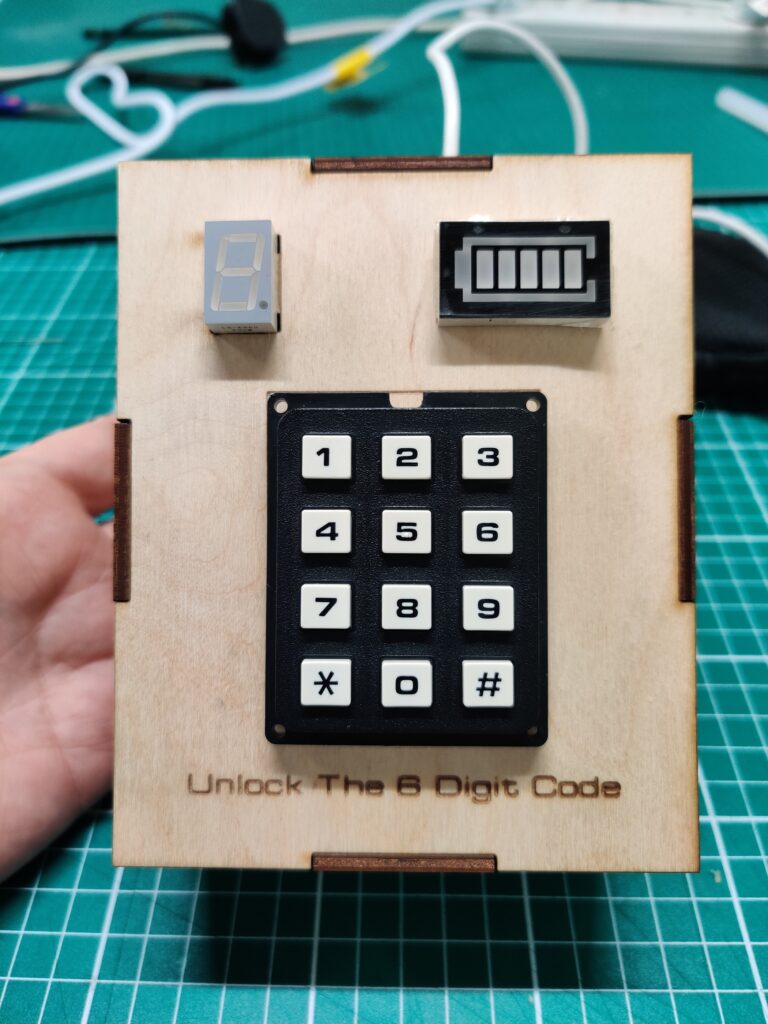
I have a love of making interactive games for science and maker events, but in the past, they tended to be big things that would no way fit on a desk. I decided to build a memory game using a keypad that has been in my parts bin for over five years —an old matrix keypad that I got free at some long-forgotten event.
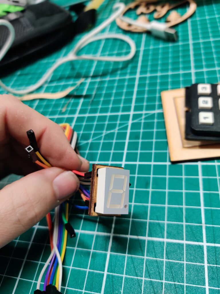
Following my normal way of working, I did a rough outline on a sheet of paper and then went searching for parts in the electronics room of Tog. I found a few different types of seven-segment displays, different numbers and an unusual battery indicator. The next step was to work on the hardware/software on the individual parts. First up was the seven-segment display.
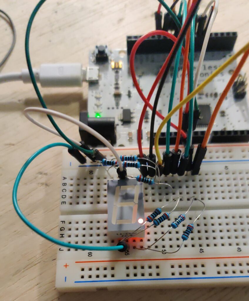
I picked a segment display; there were two of them in the parts drawer in case of any mishaps. It’s a common seven-segment with a decimal point, featuring a common cathode configuration and straightforward wiring on a breadboard. Using an easy-to-use Arduino library called AdvancedSevenSegment, the coding element progressed quickly.
Continuing with the theme of LEDs, the next element to examine was the battery level indicator display. It came with a little sheet of paper in the bag containing a circuit diagram. This part has a common anode configuration.
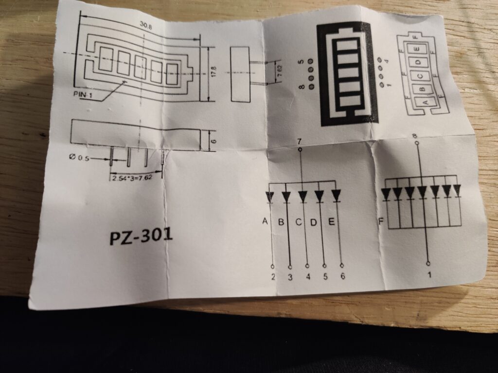
I devised a straightforward method to loop over all the elements, testing each of the LEDs since there was no library available for this particular component.
With two parts of the project successfully tackled despite the limited time invested, the keypad section was next in line. This is where the challenges began to surface. Having never worked with a matrix keypad before, I delved into some documentation and came across a library called Keypad. However, as I followed a tutorial on wiring up the keypad, a sudden realization hit me – my Arduino Leonardo had run out of digital pins. I attempted to use the analogue pins, but even then, I was one pin short.
In an ideal scenario, I would have had options, such as using a GPIO extender or another microcontroller with more IO pins. However, it was now 6 pm on a Sunday. Considering my options, I recalled the decimal point on the seven-segment display and contemplated using it as a makeshift solution to free up enough pins for my keypad.
The next step was testing the keypad. Setting up the library with the specified number of rows and columns seemed straightforward at first—assigning each key its grid location. However, I encountered a problem: my keys weren’t in the expected places. Despite remapping the keys, I struggled to get the last row of the keypad to function correctly. This marked the beginning of the time-consuming phase of the project. I spent two hours trying various approaches—rewriting code, repeatedly reading the datasheet, experimenting with different libraries, watching YouTube videos, and mostly chastising myself for starting the project so late.
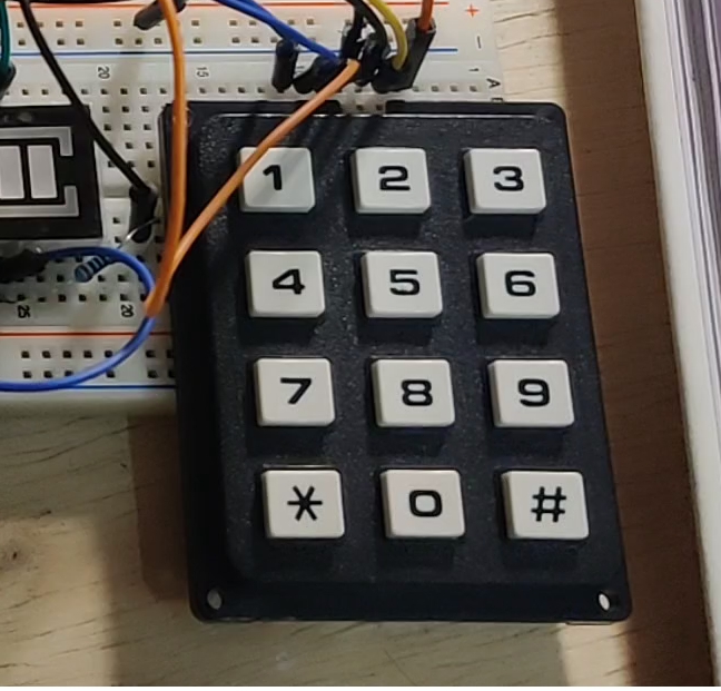
Frustrated but determined, I decided to return to basics and focus on the smallest testable element: a single button. I managed to get the number three working. However, when I moved on to map the number two, I noticed that seven was being returned. A sudden realization struck me—maybe my rows were columns, and my columns were rows. Most online examples were for cheaper keypads, not the more expensive part I was working with. This realization turned out to be the problem, and from there, progress came quickly.
I coded a simple program that displayed the entered number on the keypad on the seven-segment display. By 8 pm, with all hardware parts prototyped and test code written, I left for home to have dinner.
I geared up to tackle the game element of the project. With a podcast playing on the TV, I opened my laptop and began assembling the components. The overarching concept of the game was to challenge a player’s memory in an enjoyable and, as much as possible, an intuitive manner. Given the six LEDs on the battery-level display, the goal was to guide the user in remembering a six-digit number.
void generateRandomNumbers() {
  Serial.println("generateRandomNumbers");

  if (!isRandomSeedSet) {
    randomSeed(millis());
    isRandomSeedSet = true;
  }

  for (int i = 0; i < numOfLevels; i++) {
    numberToEnter[i] = random(minValue, maxValue);
    if (i != 0 && numberToEnter[i] == numberToEnter[i - 1]) {
      //Loop Again - No repeating two numbers in a row
      i--;
    }
  }

  for (int j = 0; j < numOfLevels; j++) {
    Serial.println(numberToEnter[j]);
  }
}
The initial challenge in coding the game was figuring out how to generate a random number. Having previously used the random() function in Arduino, I was aware that it needed to be seeded with the noise from an analogue input. Unfortunately, I had already exhausted all available analogue inputs. An old forum post came to the rescue with a suggestion—using the amount of time in millis() that it takes for a user to press a button after the Arduino is powered on. I won’t delve into every detail of the code from this point forward. I systematically built up the game, adding one function at a time, and layering them until I had a fully functional game.
Monday arrived, and I managed to persuade my brother to playtest my prototype over breakfast, just to confirm if anything tangible had come out of that late-night coding session. With his confirmation that indeed it was a game, Monday night’s electronics session at Tog became my last opportunity to transform the prototype into a desk toy.
The remaining tasks included transitioning from a breadboard to a shield and laser-cutting a case. I set up in the common room of Tog, where Electronic group nights are open to both members and the general public. Initially, I had planned to assist a member with a Pi project and welcome a few first-time visitors on the same night, all before remembering I had this project to finish.
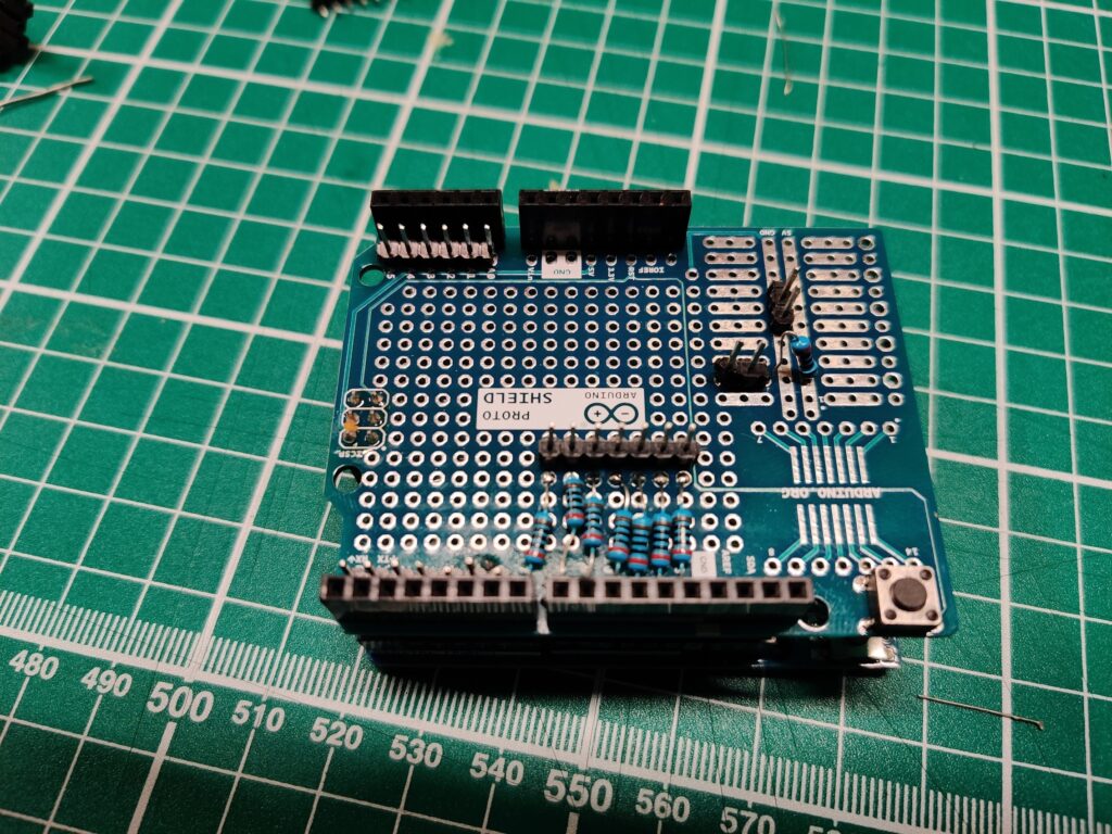
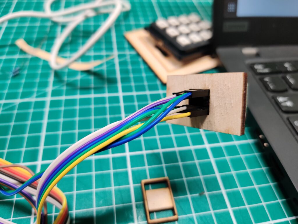
The process of transferring the circuit to the shield required meticulous soldering of resistors and header pins, with constant double-checking of the pinout, as there was no room for a do-over. Despite this potentially time-consuming task, it only took an hour. However, as is customary during group nights, my time is not entirely my own.
By some mysterious turn of events, it was now 9 pm, and I had just begun contemplating the design of a case. Following the same approach, I decided to begin with the individual parts, considering them one by one before envisioning the whole.
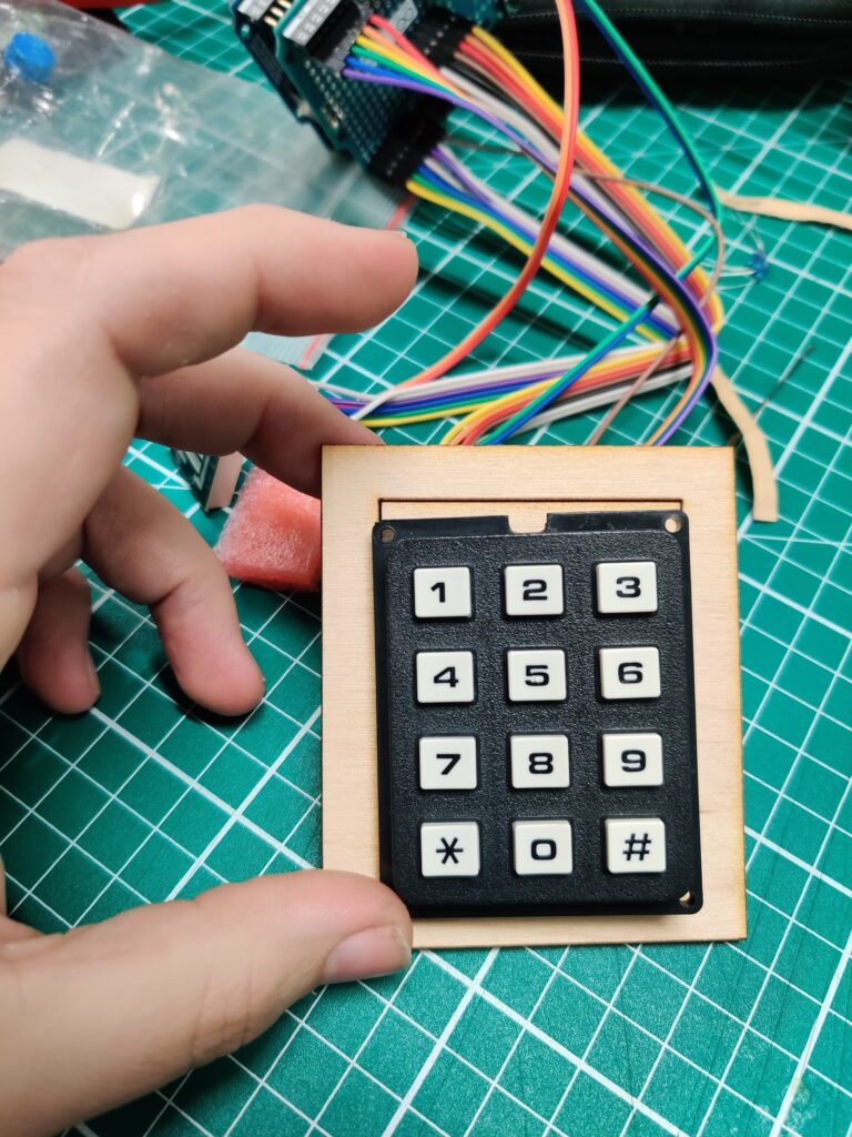
I soon found myself alone in the hackerspace as people started to head home for the evening. However, that wasn’t an option for me. By 11:30 pm, I was content with the design of the faceplate for the desk toy. I then proceeded to use MakerCase to craft the overall box element.
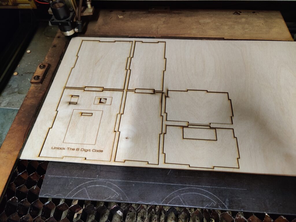
I’m not a woodworker, and this skill is currently outside my expertise. Evaluating my go-to building method, I settled on using hot glue. Over the next 90 minutes, I wired and glued the box together. The final step was placing the top section of the box. Whether it was due to my increasing fatigue or if I designed it with only a thin piece of wood where the USB comes out, I accidentally snapped the part.
Undeterred, I got back on my feet, laser-cut another top plate, and with the utmost care, I installed the final face.
After a few playthroughs, one of them recorded above, the project was complete. I locked up the space and bid farewell at 2 am.
Participating in the Secret Santa was a rewarding experience. Crafting a project for someone I didn’t know posed an interesting challenge. For additional photos from the build, you can check our gallery.
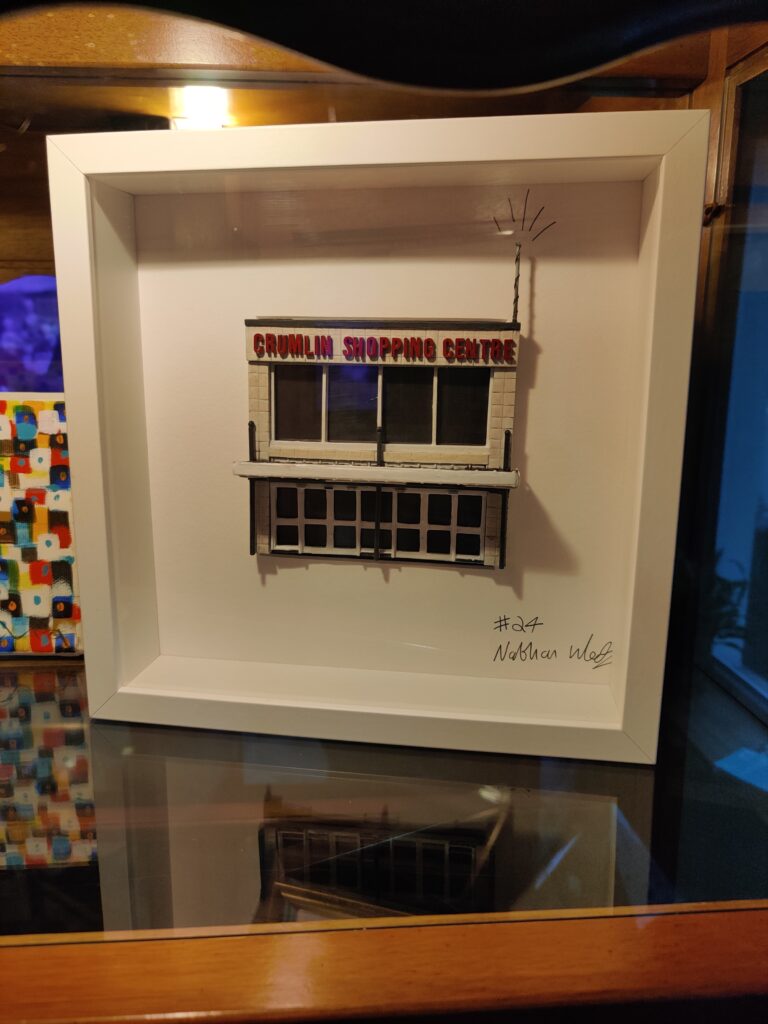
Now, onto the gift I received. My good friend Nathan took on the task of creating something for me. Aware of my longtime residence in the Crumlin area and my appreciation for a good joke, he crafted the infamous Crumlin Shopping Centre (you can check out the famous parody account on social media).