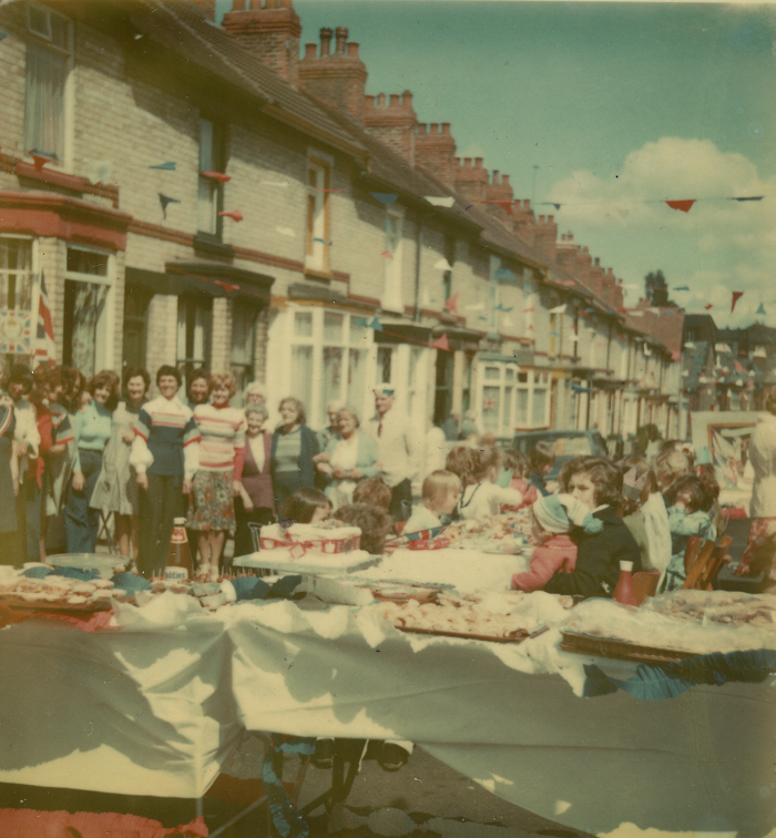
!!!BIRTHDAY PARTY!!!: Tog will be ten years old this month, to celebrate we’re turning our customary Open Social night into a Party night. Saturday 26th January from 7 pm onwards, everyone welcome!
Lock Picking: Happens on Mondays, 7th and 21st January from 7 to 9 pm, or until we’re tired and need to leave. Learn how to open a variety of padlocks harvested from the Halfpenny Bridge – handcuffs too, you never know when that may come in useful. Tools and expertise on hand, and basic lock picking sets are available for purchase, 16 euro each.
Coding: Runs on the same Mondays as lock picking, the 7th and 21st January at 7pm. Come down and work on a project or help others with theirs. Don’t forget to bring a laptop.
Craft Night: Every other Wednesday, the 9th and 23rd January at 7pm. Bring along an unwanted Christmas present and hack it into something cool. Or knit, sew, crochet, embroider, glue, fold, cut and solder away. We have sewing machines, a laser cutter and a 3D printer for the ambitious.
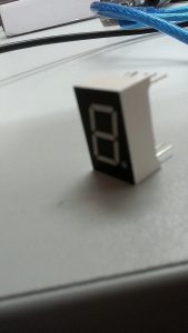
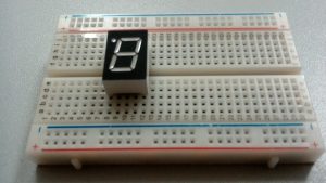
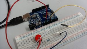
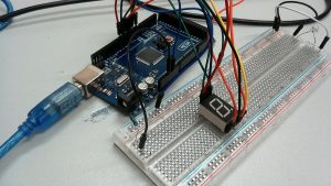
Electronics and Micro Controller Night: Runs every non-lock-picking Monday, the 14th and 28th January at 7pm. For all levels: Arduinos, Raspberry Pis and Intel Galileos, try our introduction to electronics worksheet. Some basic electronics kits available for sale. Bring your own laptop or notebook computer.
Wikipedia Editing: learn how to contribute to the world’s most useful and most searched online encyclopaedia. This month we are celebrating the 15th anniversary of Vicipéid, the Irish language Wikipedia, there will be cake and “other party elements”. Intrigued? Come along, Wednesday 30th January, 7pm onwards.
The Science Fiction Book Club elbows its way back into your frontal cortex this month, we’re reading Neal Stephenson’s Snow Crash. We will be praising / trashing it on Wednesday 30th January from 7pm.
 ional woman on telly how to really craft Christmas. Or knit, sew, crochet, cut-fold-glue-solder to your heart’s content. We have sewing machines. We also have laser cutting and CNC routing expertise. We may soon have a 3D printer.
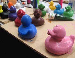
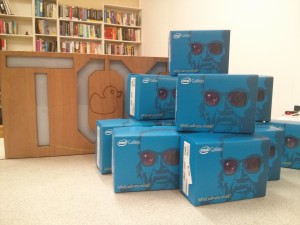 We have graciously received a donation from