 Once upon a time, TV repair shops were everywhere. Now there are hardly any left. There are reasons for that, probably based on a mix of cost, reliability of electronics, and a throw-away culture. Even in the few TV repair shops that are left, would anyone actually take a scope, schematic and a soldering iron to a TV these days? Maybe they would just replace the circuit board or display.
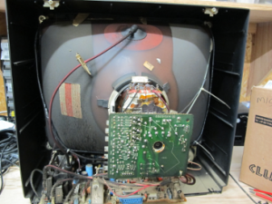
This is a tale of a Sanyo TV, made in the UK in ~1992, based on the date codes of the components inside. It has worked continuously since then. Lately the picture has gone a bit red-ish. The TV was recently replaced by a new flat screen TV, so we’ve had a chance to take a look inside. This is the first time that the back has been off since manufacture….. ~25 years ago. Depending on your point of view, you might think that 25 years isn’t that long, but it’s not too bad either for a CRT-type TV, considering also that it has never needed a repair. If you have some other electronics that has been working without repair for a very long time, we’d be interested to hear.
Inside it is remarkably clean. Apart from the one on the tube, everything else is on a single circuit board. If the tube is not the cause of the reddish picture, then this TV is probably repairable. Some further investigation is pending. If you’d like to take a look, drop into our regular Electronics, Microcontroller and IOT evening which takes place every 2nd Monday.

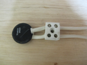
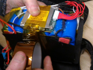 We’ve posted before about our tinkering around with Ebikes. One of our members had a faulty Ebike battery. Opening it up, the battery management circuit was found to be toast. We sourced a new one online from China, fitted it, and the battery is back up and running. We are thinking of making some spare batteries from old laptop batteries. We’re also thinking of having a TOG loaner Ebike. If you have any old laptop batteries that you could donate to us, we’d be interested. If you’d like to take a look at our Ebike works, drop in to our regular Monday evening Electronics night.
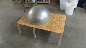 Back in our Chancery Lane days we made a very successful pizza oven. It became a regular feature of our monthly Open Socials. In late 2015 we moved to our fantastic new space in Blackpitts. One thing we don’t have in Blackpitts is our own dedicated outside yard. We can do things outside, but it is a shared car park so we can’t leave things out there. This means that we’ve had to build our oven every time and take it down again, for special occasions like our annual birthday party or summer post-Dublin Maker BBQ.