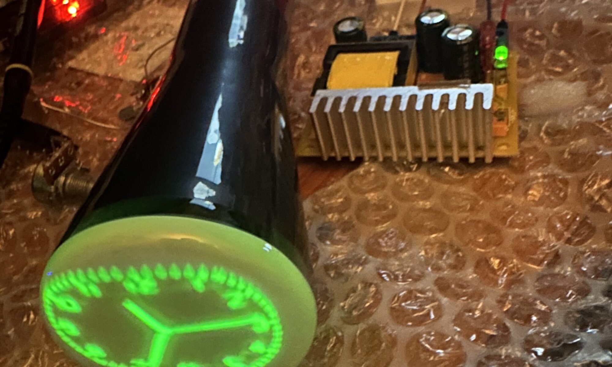
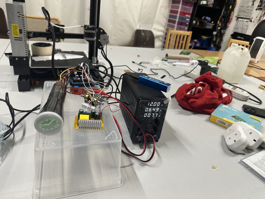
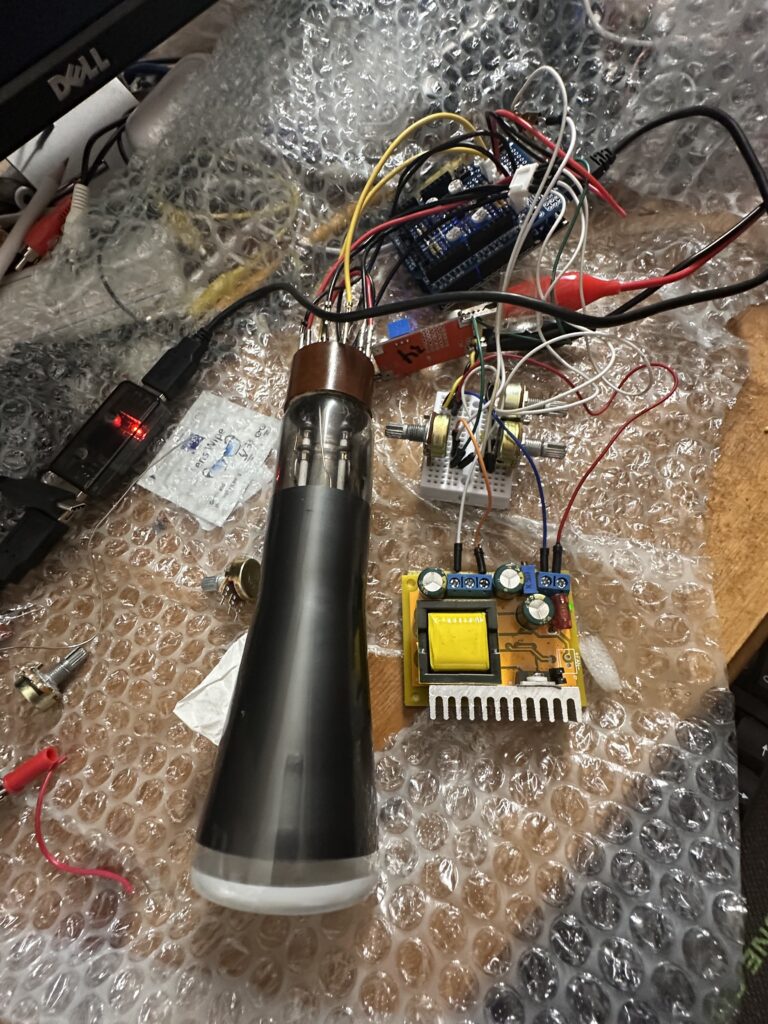
At last night’s Electronics Night in Tog Hackerspace, one of our members brought in a brilliant build: an old oscilloscope CRT tube running at ~750 V (stepped up from 12 V) with a custom deflection circuit. An ESP32 drives the X/Y plates with ~200 V deflection signals, running a tweaked open-source vector clock. They even used AI to analyse photos of the circuit and suggest fixes—super handy for fast iterations.
What’s next?
Build a wooden/perspex case
Add a weather display mode 🌦️
More vector art experiments
Huge thanks to everyone who dropped by to brainstorm and test. If you’ve a half-finished idea, odd component, or smoky breadboard—bring it along!
📍 Electronics Night: every second Monday, 7pm at Tog Hackerspace 📸 Photos in the comments.
When you think of fairgrounds or arcades, you often picture the classic “hammer strength” game – swing a mallet, ring the bell, prove your power. For Dublin Maker this year, I wanted to flip that idea on its head – literally. Instead of smashing something down, players pull upwards against a resistance. That’s how the Reverse Hammer Machine was born.
It’s part carnival attraction, part engineering challenge, and part community experiment in building something a little quirky, a little geeky, and a lot of fun.
The Concept
The idea was simple:
Replace the hammer strike with a pulling action.
Use a Bluetooth-enabled crane scale to measure how much weight someone can pull.
Display the results on a big screen so everyone around can see the outcome.
Rather than brute force through a mallet, the machine measures grip and pull strength. It’s surprising how competitive people get once the numbers are up in lights!
How It Works
The machine looks like a cross between a fairground attraction and a maker project gone wild. Here’s what’s inside:
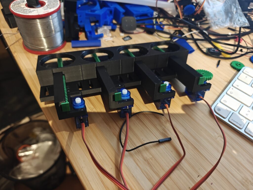
Bluetooth Crane Scales – these are normally used in warehouses or for weighing heavy loads. I hacked one into the system to register the pull force. Aliexpress special
ESP32 Controller – a small but mighty microcontroller that handles the Bluetooth connection, reads the data, and passes it on.
LED Strip – mounted along the board to give a visual indicator of how much force is being applied. The harder you pull, the higher the light climbs.
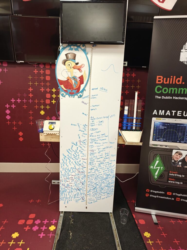
Display Screen – the live weight reading is shown on a large monitor, complete with a fun duck mascot illustration for a playful touch.
Players grab the rope, pull upwards, and watch their strength measured in real time. The numbers shoot up on screen while the LED strip glows higher and brighter – instant feedback, instant bragging rights.
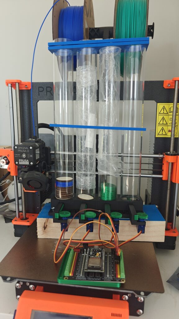
The Build
I built the frame tall and sturdy, with enough presence to attract attention across the room. The whiteboard-style front not only holds the LED strip but also doubles as a canvas for signatures and doodles from players.
For more photos of the build, check out our gallery.
oplus_3145730
Some key features of the build:
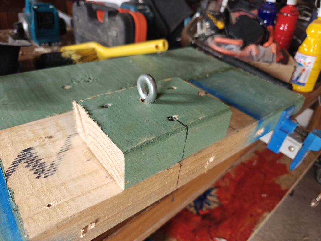
Mechanical setup: The rope feeds through a pulley at the top so players can get a good pulling grip.
Electronics box: A control panel with a button and a microcontroller sits neatly to the side.
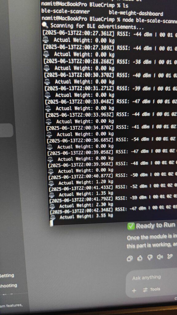
Data display: The Bluetooth scale readings are processed by custom code and displayed on the big screen with graphics.
The artwork – a cheerful duck in a top hat – was added to keep things light-hearted and tie in with the playful Dublin Maker spirit.
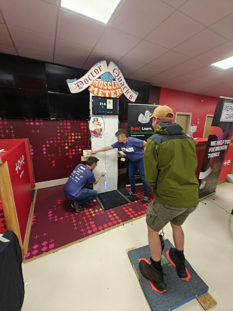
On Show at Dublin Maker
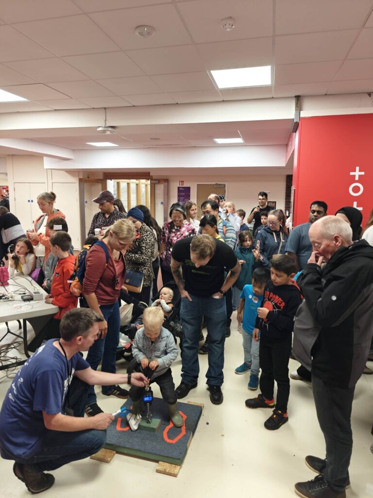
The Reverse Hammer Machine made its public debut at Dublin Maker, where visitors of all ages lined up to test their pulling power.
oplus_11534368
Lessons Learned
As with any maker project, there were a few quirks and challenges along the way:
Bluetooth quirks – the crane scale wasn’t exactly designed to be hacked, so getting stable data required persistence.
User safety – people can pull harder than expected, so making sure the frame was strong enough was a priority.
Showmanship – it’s not just about the electronics, it’s about making it fun and inviting to play and the competition of competing against family and friends.
By the end of the day, the board was covered in names, the LED strip had seen plenty of action, and the duck mascot had overseen countless strength contests.
Why Build It?
The whole point of Dublin Maker is to share creativity, curiosity, and the joy of making. The Reverse Hammer Machine isn’t just about strength – it’s about turning an idea into something physical that makes people smile.
It blends hardware hacking, coding, design, and a touch of carnival silliness into one interactive exhibit. Best of all, it gets people talking, laughing, and competing in the spirit of fun.
oplus_11534368
What’s Next?
I’d love to refine the project further:
Add a leaderboard system that stores top scores during the day.
Integrate sound effects for dramatic impact when someone hits a new record.
Maybe even design multiple “difficulty modes” with adjustable resistance.
The great thing about projects like this is they never really finish – there’s always another upgrade waiting to happen.
Bringing It All Together
The Reverse Hammer Machine shows what can happen when you take a familiar idea and twist it. By hacking together a Bluetooth crane scale, some microcontrollers, and a splash of creativity, you end up with something that feels both retro and futuristic.
It’s a reminder that engineering doesn’t have to be serious – sometimes the best projects are the ones that make people grin.
One of the projects I’ve been meaning to tackle is a walking cane for my girlfriend, who sometimes needs extra support when moving around. It’s not just another workshop job; it’s important, so I wasn’t about to risk good timber on a first attempt. Before I even acquired a cane stock, I figured it made sense to spend some time wrestling with a tool that was still new to me: the wood lathe.
Since this was my first real spin at it, I started with softwood scraps. Honestly, the results were pretty rough. Tear-out everywhere, edges that looked more chewed than cut. Still, rather than chalk it up as a failure, I treated it as an early lesson. A quick trip for some denser hardwood planks gave me the excuse to keep going, and that’s when things took an unexpected turn.
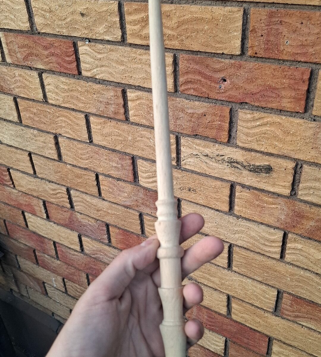
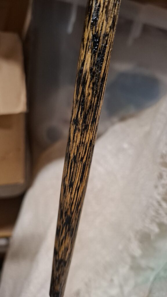
What started as a test run slid sideways into a completely different project: wizard wands. With the lathe humming, I worked a pair of blanks down until they began to resemble something out of a fantasy film. To push the texture further, I brushed the grain with a wire brush, stripping away the softer fibres so the harder ridges stood proud. It made the timber beg for a good finish.
Painting and sanding became their own experiment. Both wands got a base coat, one solid black, the other black with flashes of red. After the paint set, I sanded them back so only the recessed grain kept its colour. The raised lines popped as raw wood while the grooves glowed darker. One wand ended up stained a deep brown, giving it an old-world look. The other I sealed with clear lacquer, which left the contrast sharper and cleaner.
The finished pieces? Two handmade wands, each carrying its own quirks, the sort of thing a kid (or a nostalgic adult) could wave around and feel a spark of magic. More importantly, they gave me a crash course in shaping, texturing, and finishing on the lathe, without the pressure of messing up the cane wood.
So the cane is still waiting, but now I’ve got a pair of unexpected practice pieces and a much steadier hand at the lathe.
And if you’re curious what others are up to in the workshop, there’s always something brewing, sometimes practical, sometimes just for fun. Keep an eye on the blog, or better yet, swing by on an open night and see for yourself.
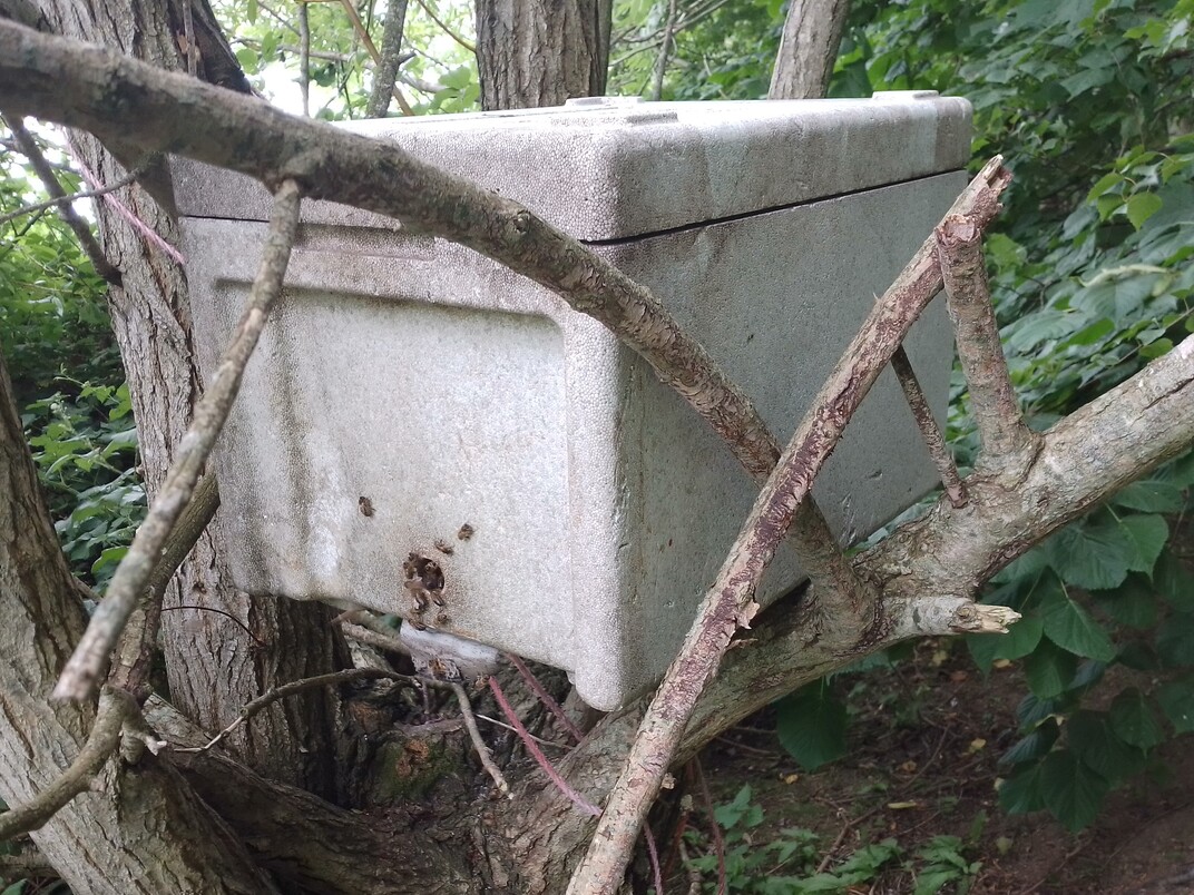
Beekeeping is one of the many and varied interests of TOG members. Our member John is a keen beekeeper, and he recently captured a swarm to create a new colony.
As the number of honeybees in a hive increases, the usual natural way to prevent overcrowding is by swarming. A few scout bees will find a new location, and the old Queen will leave the hive with about two-thirds of the bees. They often cluster on a tree branch before settling into a new location.
One way to catch a swarm is to put a box containing comb frames in a tree. Drops of lemongrass oil act as an attractant because they resemble the pheromone of a Queen bee.
In this case, a swarm of honeybees have gathered under the box, rather than inside. These bees were removed by gloved hands and placed in the box. The Queen will start to lay eggs and establish a new hive. The bees remaining in the old queenless hive will raise a new virgin Queen who will fly out, get mated and return to lay eggs.
Taking some inspiration from our aquarium project in the space, John is planning a monitoring project for a hive, including some sensors and a camera to watch the bees remotely.
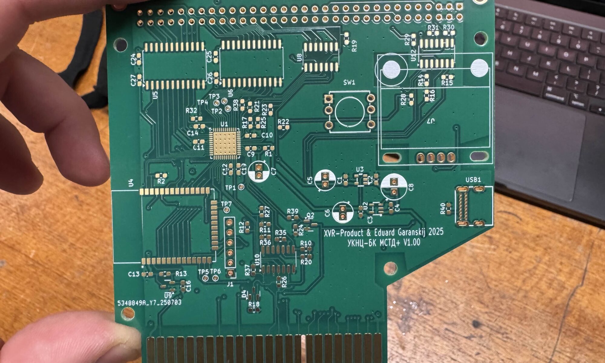
Over the years, I’ve collected several rare machines and long dreamed of building add-on devices for them, something to expand their memory or load software from modern storage devices like SD cards, or even over Wi-Fi. These vintage devices typically load from tape or floppy disks, which is a painfully slow process. However, due to a lack of time and experience with complex electronics, I hadn’t been able to complete any such project.
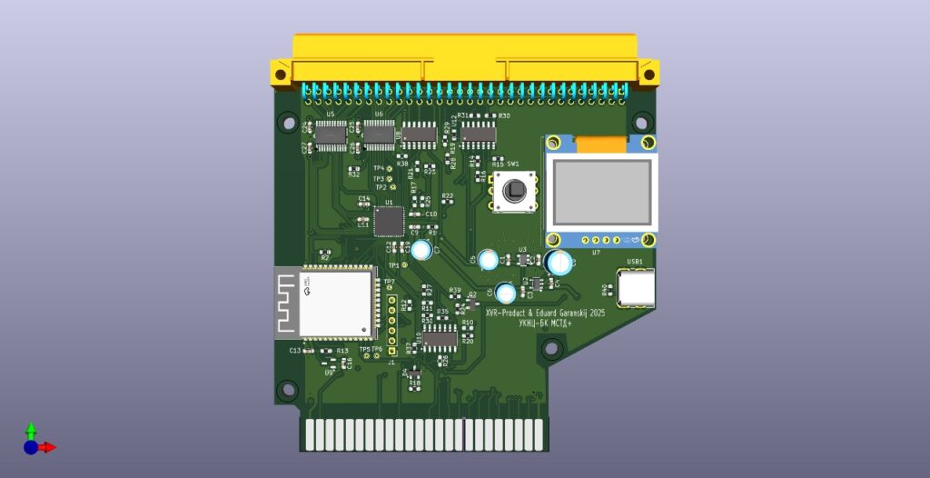
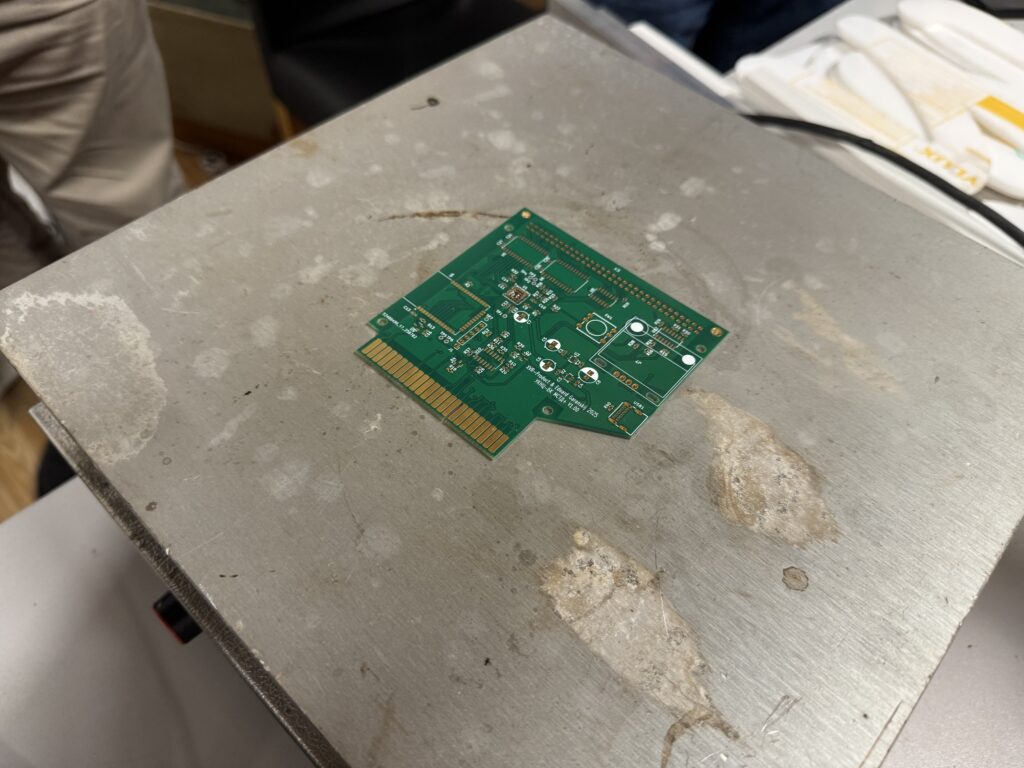
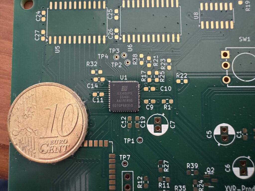
That changed last month when I met Roman, a new TOG member. He offered to help and turned out to be much more experienced in electronics design. Using KiCad and modern components like an FPGA and ESP32, Roman designed a custom board. These chips are incredibly small and require special tools and techniques to work with.
We had the board manufactured at JLCPCB.
While I have a general understanding of electronics, I had never soldered such tiny components before. Roman had some experience with small parts, but even for him, this was a new level of precision.
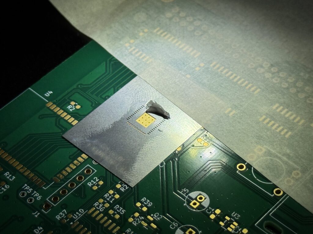
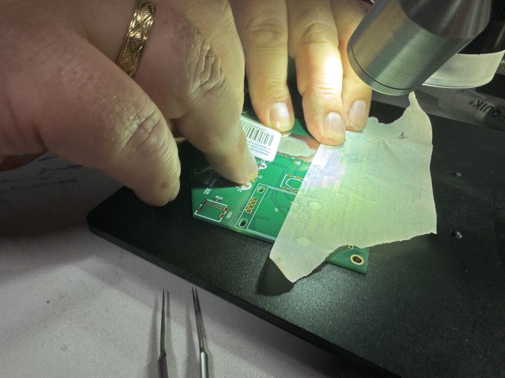
We found a preheating plate at TOG and ordered a stencil to apply solder paste. Yesterday, we met at the space to try soldering the smallest chip on the board.
The first step was applying the solder paste using the stencil. This turned out to be trickier than expected. We had to align the stencil perfectly with the board’s pads, spread a thin, even layer of paste, and carefully lift the stencil without smearing it. It took us several tries. Sometimes the stencil shifted, and other times we applied too much paste.
Before soldering the actual chip, we did a test run on a spare board without placing any components, just to see how the paste would behave during reflow. That helped us understand how the solder would spread and whether it would stay properly on the pads. It was a useful trial that gave us more confidence before working with the real part.
Eventually, we decided to go ahead and solder the chip, even though some areas had a bit more paste than ideal.
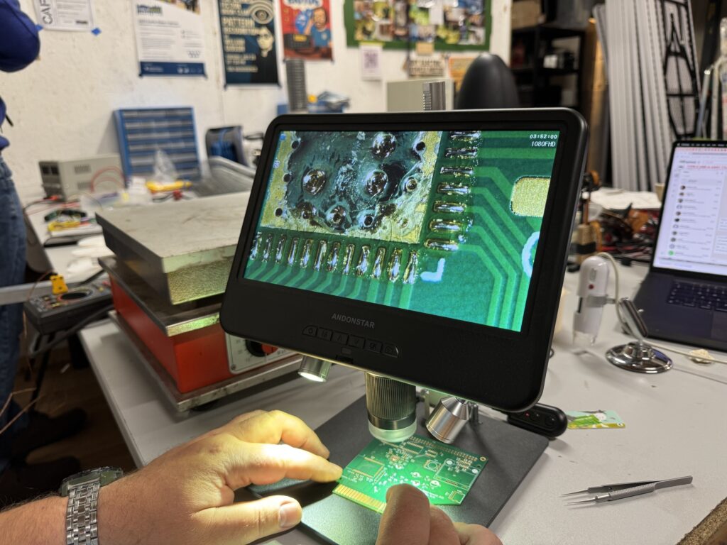
We used a special hot plate that gradually heats the board to around 240°C. As it warms up, the solder paste melts and flows onto the pads, guided by surface tension.
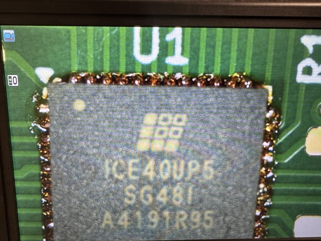
The process is slow, so the whole operation took a while. But in the end, the chip was successfully soldered. You can see it in the photo, though there’s still some leftover flux that we’ll need to clean off with isopropyl alcohol. Unfortunately, we ran out of time on Monday evening, so that step will have to wait.
We can’t fully test whether the chip is working yet, as other components on the board still need to be soldered. However, we’ve checked for shorts between adjacent pins, and everything looks good so far.
This was just the first step, but it already feels like a big achievement. With a bit more work, we hope to bring some of these old machines back to life, with modern upgrades that keep the retro spirit alive.
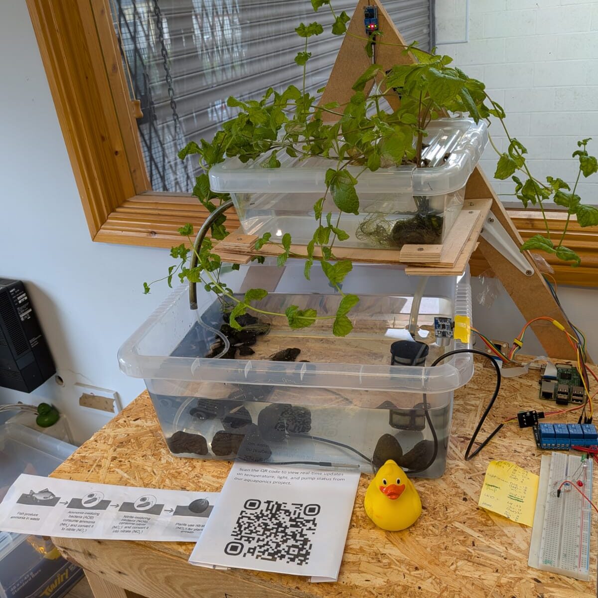
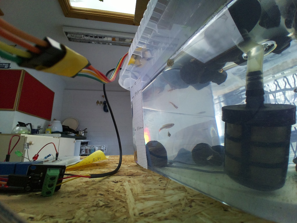
Check out this cool aquarium project by our member Hussam. This is an aquaponics project called ”PIPONIC”. The system can be monitored and controlled remotely. Aquaponics combines fish and plants in one self-sustaining setup. In this case, the fish and plants are goldfish and mint.
The system runs on a Raspberry Pi 3, with a few key components: • A light sensor that turns on LEDs in the dark • A 12V water pump that cycles on/off to keep the water moving; • A MAX31865 sensor that monitors water temperature for the fish (16–24°C); The system logs data to a CSV file and sends it to Hussams website via an API for real-time monitoring. A camera connected to the Pi allows a visual check the water level.
Hussam is currently working on automating the water level and would love to team up with others to explore new ways to expand the system and make it even more sustainable and smart. TOG has been the perfect place to experiment, learn and share creative ideas about projects like this. The aquarium is in our kitchen in the space. You can usually find Hussam at Electronics Night on Mondays. Feel free to drop by if you’d like to chat, share ideas, or collaborate on improving the system!