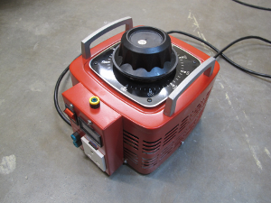
Actually there was nothing wrong with it. It didn’t really need “fixing”. A variac is a kind of variable AC transformer. They are very useful for testing AC loads because they can give a variable output voltage usually from 0 up to some value. This particular one can output from 0 to 250V and supply about 12A of current.
It is rated at 3kVA which is quite a bit. A big horse of a transformer like this has a big inrush current when it is plugged in. The surge is so great, that it was tripping the circuit breaker on our distribution board. The breakers on TOG’s board have C-curve trip characteristic, so they’re really not suited to this kind of load.
So something had to be done to limit the inrush current. We thought about a power resistor and a shorting relay, but in the end opted to try an NTC type surge limiter. This is a type of resistor where the resistance falls with temperature. At room temperature the resistance measured was about 12 ohms. The resistance falls rapidly as the temperature rises. Even so, the thing gets hot at heavy load. We used the 2kw heatgun as a heavy test load. We mounted the limiter high up inside the enclosure, in free air. Plenty of insulation and some cable ties to secure it. Tested it and no tripping now. A bit more testing is required however. particularly at higher currents. Need to do some I²R calculations and temperature measurements. Pics here.
At long last I have proof that variancs exist and are living in Ireland! I have been making enquiries about these and meeting blank looks. Super job!
[…] solution was a simple one, they fitted an NTC surge limiter in series with the variac input. This is a thermistor whose resistance falls with temperature. Thus on start-up it presented an […]
[…] solution was a simple one, they fitted an NTC surge limiter in series with the variac input. This is a thermistor whose resistance falls with temperature. Thus on start-up it presented an […]
donal
i bought a nice variac from a man in kilkenny a few years ago. he built it himself.. spent an interesting couple of hours chatting with him about stuff. really nice guy, knows his stuff. http://www.thedimmerchannel.com/ is his site. he seemed up for building more, or he may just have more. and here is a poor photo of the one i got from him, on my super messy bench. http://i.imgur.com/BRp45xO.jpg
Hi, about the “C”-type fuse characteristic: AFAIK, in new household installations, the EN IEC 60898-1 “B” type, which is the even more sensitive variant, is the most common type used. This is because you can tolerate a higher loop impedance in that case, and you gain a bit of extra-safety. So the “C”-type breaker is not that “unsuited” for the task.
Have you considered putting an IGBT based current limited instead? Some tweaking of this circuit could also give controlled current limiting and overload protection http://www.radiolocman.com/shem/schematics.html?di=69966
I hadn’t considered anything like that. I had thought about combinations of relays, timers and power resistors. Trouble is that there is very little room available inside the case and I didn’t want some kind of external box. Thanks for the link though. It looks interesting. I might lash one together and see how it performs.